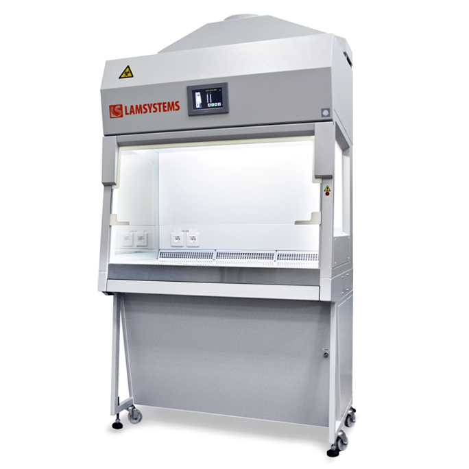

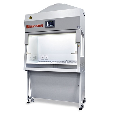

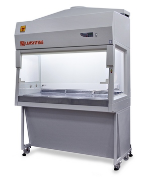
Biological Safety Cabinet BMB-II-"Laminar-S."-1,2 SAVVY Class II Type B2
Class II Type B2 Biosafety Cabinet ensures environment, product, and personal protection during lab procedures where the circulation of filtered air is restricted due to the existence of possible chemical fumes that are released during the process. Since the filter does not catch these chemical fumes, it can be of potential danger to the operator if they are re-circulated in the workspace. Therefore, Class II Type B2 Biosafety Cabinets are ducted to a blower that is located on the outside of the cabinet, for total exhaust.
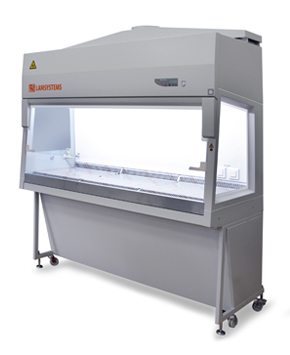
Main parameters and dimensions
Microbiological safety cabinet BMB-II-“Laminar-S.”-1,2 SAVVY B2
Class II
| Article | 2Е-В.003-12 |
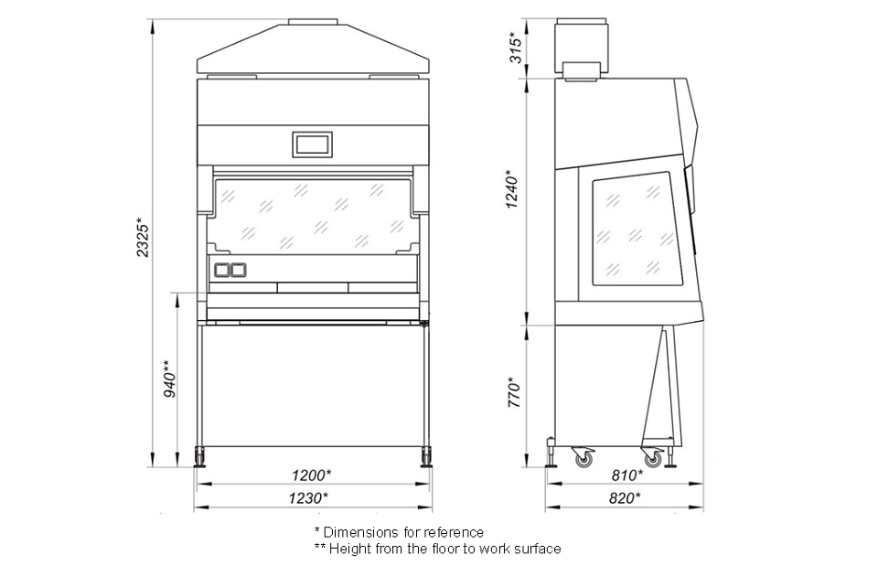
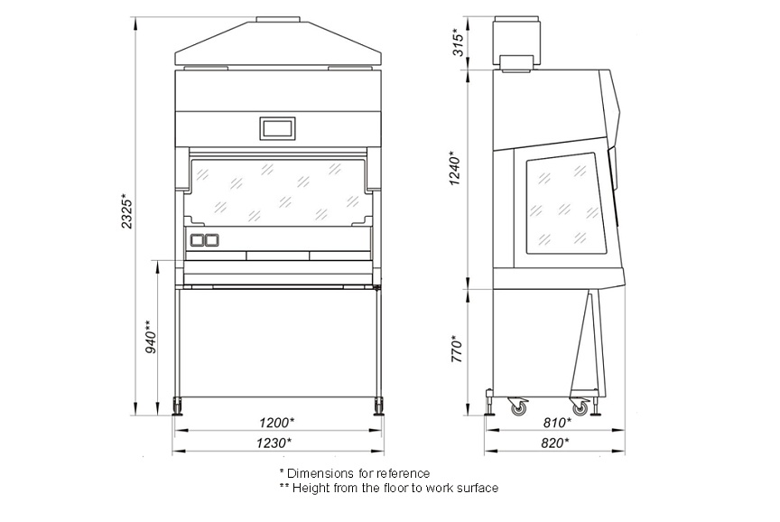
| Dimensions of the assembled cabinet with exhaust hood, mm (WхDхH)* | 1200х810х2325 |
| Dimensions of the cabinet’s work chamber, mm (WхDхH) | 1105x610x705 |
| Mass of assembled cabinet with the stand, kg, not more than | 270 |
| Input power of the cabinet (exclusively of the load on the built-in outlets), W, not more than | 730 |
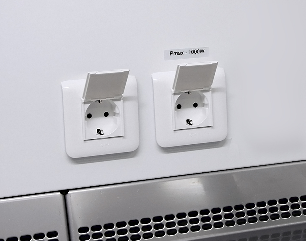
| Maximum load allowed on the sockets, W | 1000 |
| Air volume supplied to the work chamber of the cabinet, m3/h | 795-820 |
| Air volume exhausted from the cabinet, m3/h | 1180-1220 |
* dimensions do not account for outstanding supports
ATTENTION! The cabinet must be connected to an individual active exhaust system with a flow rate of 1135-1205 m3/h. The room where the cabinet is installed must have a supply ventilation system with a flow rate of not less than 1000 m3/h.
MAIN CHARACTERISTICS
| Installation work chamber air cleanliness class for suspended particle (aerosol) concentration as per ISO 14644-1 | |
| -for particles of 0.5µm and more | ISO 5 |
| -for particles of 5.0µm and more | ИСО М (20; ≥ 5 мкм);LSAPC |
| Class of the cabinet according to EN 12469-2010, NSF/ANSI 49 | II |
| Type of the cabinet according to NSF/ANSI 49 | B2 |
| Class of the installed in the cabinet НЕРА-filters according to EN 1822-1 | H14 |
| Class of the installed preliminary filter according to EN 779 | G4 |
| Average downflow velocity in the work chamber, m/s | 0,35+0,01 |
| Average velocity of the air inflow though the work opening, m/s, not less than | 0,53±0,02 |
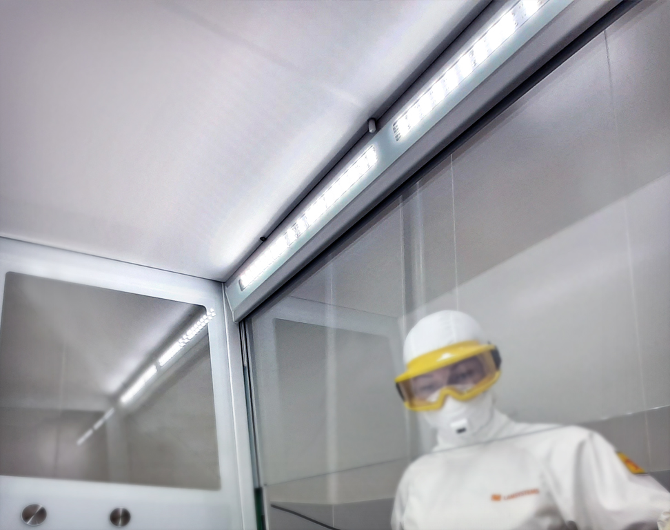
| Illuminance level in the work zone, lux, not less than | 1000 |
| Air recirculation rate in the cabinet, % | missing |
* dimensions do not account for outstanding supports
Dimensional drawing
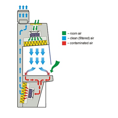
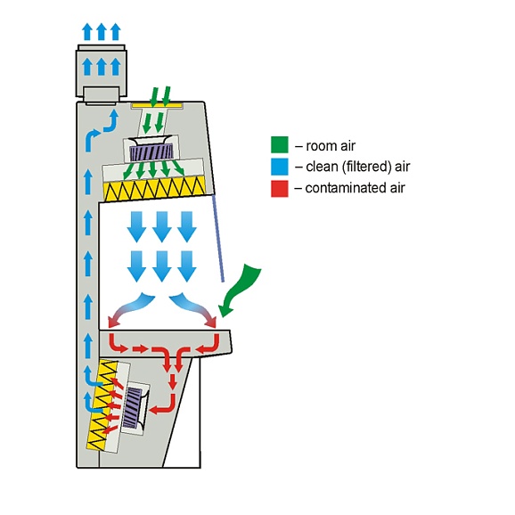
Air flow scheme
Standard Configuration
WorkChamber
- hinged front sash made of laminated safety glass; opening, closing and upholding is carried out by gas springs;
- damper against front sash closing impact;
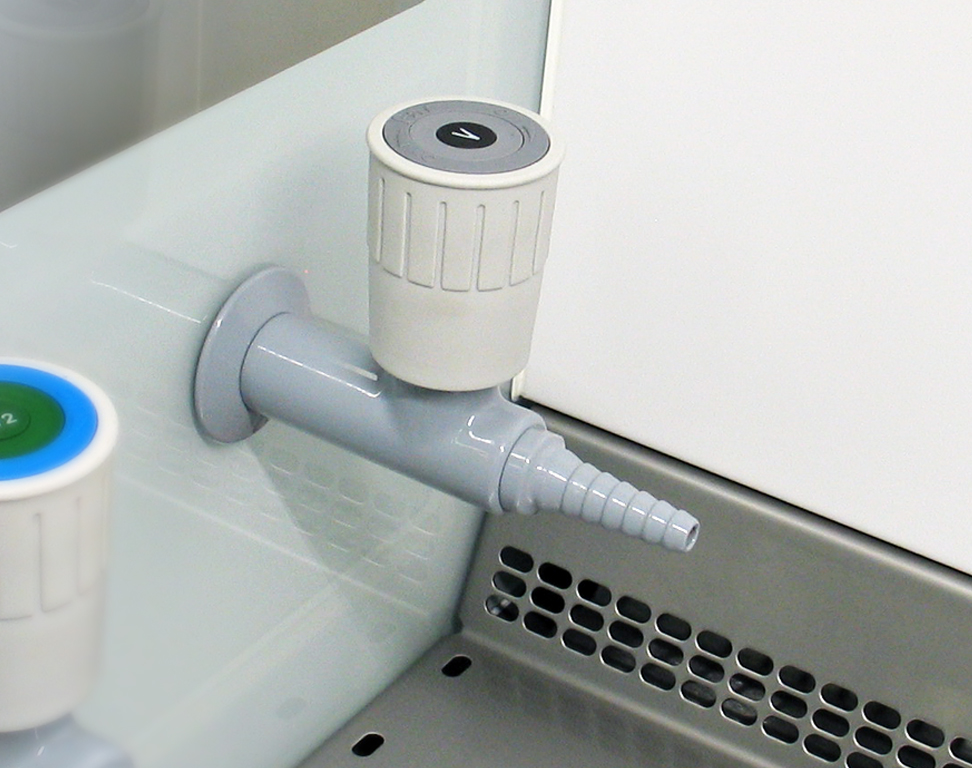
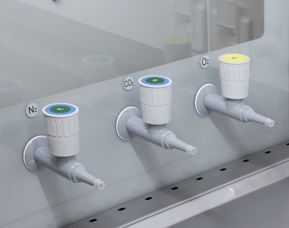
- side windows made of tempered glass: with tap ports on the left, solid on the right;
- slanted front surface of the cabinet;
- work chamber LED lighting;
- two electric sockets in the work chamber;
- airflow laminarization screen made of polymer micromesh;
- three-section tabletop made of stainless steel (AISI 304) with air intake grille in the front;
- work chamber tray made of stainless steel (AISI 304);
- removable armrest made of stainless steel (AISI 304)
UV unit
- pullout (when inoperative, is stored outside of the work chamber under the tabletop);
- metal grille protecting the UV lamp;
- dampers against any impact upon lowering the work opening screen.
Supply and Exhaust Air Filtration System
- two-stage filtration of the air coming into the work chamber: prefilter G4 and supply HEPA filter H14 located over the work chamber;
- exhaust air coming out of the cabinet is cleaned by exhaust HEPA filter H14 located under the work chamber base;
- removable exhaust hood for connecting the cabinet to the active exhaust system; the exhaust hood is equipped with joint clearance that prevents any impact of the exhaust system on the cabinet’s operation.
Control System Components
- microprocessor control system;
- touchscreen control panel;
- airflow sensors;
- front sash and UV unit position sensors;
- individual fuse for power supply to the main functions of the cabinet (fan, lighting, UV lamp);
- individual fuse for electric sockets of the work chamber;
- removable power cord with holder
Additional Components
- caster wheels for cabinet relocation;
- screw supports for cabinet fixation at operating site.
Components for Testing the supply HEPA Filter Integrity
built-in outlet for air sampling (below the preliminary filter G4);
Components for Testing the exhaust HEPA Filter Integrity
- built-in outlet for supplying the testing aerosol (on the right side of the outer side of the exhaust filter-fan unit);
- built-in outlet for air sampling (on the left side below the protection grille of the tray);
- built-in outlet for integral measurement of particles concentration behind exhaust HEPA filters (on the left side of the rear wall of the working chamber);
- rear panel of the exhaust (bottom) chamber is removable to ensure free access to the exhaust HEPA filter for its scanning during the integrity testing.
Additional options